Tuesday, December 8, 2009

WHAT TO LOOK FOR IN A JOINTER

           While the jointer can be used as a planer for small pieces of lumber, the principal function of  this woodworking machine is to put a straight, smooth, level edge or edges on a board in preparation for edge-to-edge glue-up. Rabbeting can be accomplished on some jointers but I prefer to use the table saw for this task. Chamfering, or making angled cuts, can be performed by tilting the fence.

          Accurate jointing or chamfering this requires that the cutter head blades be adjusted precisely with reference to the out feed table. The edge of each cutter head blade must exactly at the level of the out feed table: not above or below it. In most cases, sharpening the cutter blades requires that they be removed completely from the cutter head and then replaced and adjusted after sharpening. This is why I recommend the use of solid carbide as opposed to high speed steel blades: Carbide blades last a lot longer and that means less time and effort has to go into removing, replacing and adjusting blades. Buy two sets. That way, you can continue to use your jointer while the dull set is out for sharpening and you will always have a sharp set waiting.

          Always unplug your jointer from electrical current before attempting any blade adjustments. In my jointer, an 8” Rockwell/Delta classic, the blades are removed and replaced by using a flat wrench that came with the jointer. This wrench is used to loosen and tighten the hex head machine screws that press against the blades and hold them in place in the cutter head. It is very easy to round over the hex heads, so I am very careful not to do so. I purchased a gadget that helps me align the blades with reference to the out feed table. It magnetically attaches itself to the surface of the out feed table and magnetically attracts the blades upwards and holds them in position while I tighten the hex bolts. Each blade (there are 3 in my machine) must be in the extreme vertical position before it can be individually correctly adjusted and tightened. When all 3 blades have been set properly, they should just touch, but not lift, a flat piece of wood laid on the out feed table, extending over the cutter head. They must do this across their entire length of each blade.
 

          In a tool review at http://www.perfectwoodworking.com, I take a look at several jointers of different sizes from different manufacturers which may help you select a new jointer that's just right for you and your shop. This post was excerpted from the beginning of that series of reviews.


          Jointer size is most commonly determined by the full width of the blades (knives). A 6” jointer makes a maximum 6”-wide cut. An 8” jointer makes a maximum 8” cut and so on. It would be rare to use the entire width of even a 6” knife set at once, so the real advantage of wide knives is that you can move the fence to use a shaper place on the knife when the knife becomes dull. The wider your blades, the more use you will get out of them before it is time to re-sharpen. I usually start with a sharp blade and the fence all the way to the right end of the cutter head and move the fence, in increments, a bit wider than the maximum board thicknesses, to the left until the blades are all used up.
 

          Sometimes, with curly or wavy grain structure, you will experience tear-out from the lumber edge even with sharp knives. Sometimes you can turn the board around and run it through again backwards with very shallow cuts until the edge is fully jointed and the tear-out is gone. At other times, you may have to settle for a sawn joint made on the table saw. Usually you can make fairly good glue joints this way, if you have to, but a jointed edge is always my first choice.


          The depth of cut is determined by the height of the in feed table with reference to the out feed table. The lower the in feed table, the more wood is removed with each pass over the jointer. It is not a good idea to take off too much wood with a single pass. The chances of tear-out increase with the depth of cut and you may end up removing more precious wood than you really needed to, to get your perfect joint.


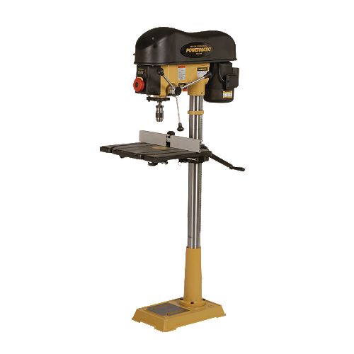
    In the jointer reviews at http://www.perfectwoodworking.com/jointerreviews, I work from the smallest up to the largest and the least expensive up to the most expensive. Those reviews include the Delta 6" Variable Speed Bench Jointer, the Jet  JJ-6CS 6" Closed Stand Jointer, the Jet JJ-8CS 8" Closed Stand Jointer, the Powermatic 8" Parallelogram Jointer, the Laguna Tools 12" Industrial Jointer and the Powermatic 16" Parallelogram Jointer.


Bob Gillespie
Woodworker
For Similar Articles and Tool Reviews see:
http://www.perfectwoodworking.com


Friday, December 4, 2009

HOW TO SHOP FOR A LATHE

          The more experience you have as a wood turner, the easier it will be to choose your next lathe. To accommodate everyone from beginner to expert, I will try to keep my comments basic and yet complete. If you are an expert, please bear with me. If you are a beginner, this post may save you a lot of headaches at the school of hard knocks. 

        I’d like to start out by saying that creating beautiful lathe turnings is an art which requires a certain amount of specialized talent. The only way for you to know if you have this talent is to take some lessons from someone who does. You can be an excellent woodworker, adept at the table saw, band saw or router and yet, you may not have the particular kind of fine touch that it takes to be a master at the lathe. Before you fork out your hard-earned dollars for a dream lathe, get some experience first.

          There are some basic things to know when shopping for a lathe and probably the most important question you might want to ask yourself is, “What do I want to produce on my new lathe?” and, “What do I think I might want to produce on my lathe in the foreseeable future?.”  If all you ever want to do is turn pencil and pen blanks, a micro lathe is all you need. If you plan on turning out huge bases for round tables, you might want to consider investing in an industrial behemoth.

          Numbers wise, you will want to consider the lathe’s bed length, the distance between the base of the tool rest and the center (diameter that can be turned), the maximum diameter of bowls that can be turned safely (usually on the outboard side of the lathe head), the horsepower and RPM of the lathe motor and the variable speed range.

          One thing that may not be immediately obvious is that all lathes create vibration. This vibration is transmitted to the point where the cutting tool touches the wood. Vibration makes for poor or rough cuts and vibration must be dampened out as much as possible. A flimsy lathe stand is not going to do this for you. I went so far as to build a heavy lathe bench which incorporated a large box which I filled with sand bags. A heavy-duty stand might suffice for you, however.


          Be sure to check out my review of six lathes, small to large, at http://www.perfectwoodworking.com/. I examine and compare the Jet JML 1014 10" x 14" Variable Speed Mini Wood Lathe, the Jet JWL-1220 12" x 20" Wood Lathe, the Delta 46-460 Variable Speed Midi Lathe, The Jet JWL-1642-EVS-2 16" x 42" Full Size Wood Lathe, the Powermatic 3520B 20" x 34 1/2" Wood Lathe and the Powermatic 4224 24" x 42" Wood Lathe.


Bob Gillespie
Woodworker
For similar articles and tool reviews see:
http://www.perfectwoodworking.com/


Sunday, November 29, 2009

DRILL PRESS REVIEW: POWERMATIC 2800 PM 18” VS DRILL PRESS

          Before we go any further and, at the risk of stating the obvious, I’d like to point out that the purpose of a drill press is to drill consistently straight holes accurately into wood, metal or plastic. The purpose of a drill press with a fence is to drill repetitive holes in a work piece at a consistent distance from the edge of a work piece. The purpose of a drill press with a fence and one (or two) stops is to drill holes at a consistent distance from one or both ends of a work piece or work pieces. The purpose of a drill press with a tilting table is to drill accurate and repeatable holes at an exact angle into the work piece. The purpose of an electric drill is to drill holes only where using a drill press would be impossible or impractical.


          There are many things to consider when comparing drill presses such as motor size, table size and features, quill stroke, task lighting, laser availability, rotation speeds, ease of speed change, number of speeds, reversible feed handle (for lefties) and even the size of the base (for machine stability).


          With regard to motor size, experience tells me that ¾ horsepower is about the smallest size motor I’d like to see on a drill press. Some models try to get away with a ½-horsepower motor. There are times, especially at higher belt speed ratios that a half horsepower motor will prove to be inadequate. 
 
          I recently completed a side-by-side comparison review of 3 drill presses for http://www.perfectwoodworking.com/drillpressreviews. This review is excerpted from that article. The Powermatic 2800 PM is, by far, the most expensive I reviewed. The other very capable drill presses in that article are Delta's Model 17-959L and the Jet Model JDP-17DX. Those models are competitive with each other and list for about half the price of the Powermatic 2800 PM.   
 
            The thing about the Powermatic is that it is just plain neat! It has all the bells and whistles a designer could dream up. The person who designed this thing clearly knows a lot about drill presses and woodworking from personal experience. If money were no object it would be the drill press I would buy. A guy can dream, can't he? Here's the Powermatic 2800 PM review:
 
 
POWERMATIC 2800 PM 18” VS DRILL PRESS


          Like any Powermatic machine, this drill press has top quality, smooth operation and features to die for. It also has a somewhat hefty price tag when compared to other similar machines. That said, let’s take a look at what you get for your money so you can decide if it’s worth making the jump.


          This machine features twin LED lights, mounted in the head that do not cast shadows, head-mounted twin lasers that pinpoint the drill point, a 16” x 14” table with twin T-slots that expands to 16” x 26” when needed to support large work pieces. The table tilts left or right 90 degrees with a positive stop at zero degrees. A large handle makes raising or lowering the table easy. An additional, unique feature that is included in the price of this machine is an adjustable split fence with a dust collection port. A fence is essential to production work so plan on buying or making one if you don’t buy this machine.


          Speeds are easily changed from 400 to 3000 RPM with a handle on the upper left side of the head, meaning that you do not need to concern yourself with belt and pulley access. And, you can tell how fast or slow the machine is running by looking at a digital speed indicator right on the front of the head. Also in the front of the head is a lighted on/off switch with a key.


          Powermatic gives you a full horsepower of motor power which insures that this machine can handle everything that is presented to it. The motor is single phase and can be run on either 115 or 230 volts AC. It is pre-wired for 115 volts.


          The 5/8” chuck is keyless, the depth stop is quick-setting and the feed handles can be mounted on the left or the right for ease of operation no matter which handle you like to use. Spindle travel is 4 3/8” for deep drilling capacity. For drilling into assembled projects, the maximum chuck to table distance is 30” and the maximum chuck to floor distance is 46”. The column diameter is 3 1/8”, the base measures 11 7/8” x 19 5/8”. The drill press weighs in at 287 lbs, and ships at 302 lbs.


Bob Gillespie
Woodworker


See the full three-drill press comparison review and many more tool reviews and articles at:
http://www.perfectwoodworking.com/


HELPFUL LINKS
(related to this post)


Powermatic 2800 PM Drill Press


Jet JDP-17DX Drill Press


Delta 17-959L Drill Press


TABLE TOPS THAT CAN MOVE

          Solid wood is sensitive to changes in moisture content and it will grow and shrink accordingly, more in terms of width than length. If you move your table from the rain forest (damp air) to the desert (dry air), it will shrink. If you move it from the desert to the rain forest, it will grow in size.


          I have made many tables in my lifetime and I learned early-on that it is extremely inadvisable to fasten a solid wood table top rigidly to the table’s apron. The table top will move over time and if the movement is significant, it will tear the apron and the table apart. That is why I make all of my tables with a dado groove near the top, inside of the apron all around. I then manufacture wooden clips that will attach the table to the apron. The clips are screwed to the bottom of the table top. A “finger” is made by cutting away part of the clip at one end. This “finger” is inserted part way into the dado in the apron before being screwed to the table top.


          Because the screw holes in the clips vary slightly in position from one clip to the next, I make a habit of marking the clips in numerical sequence with a felt tip pen. I mark the same number under the table top where it will be covered by the clip. This way, the top can be removed for refinishing and be replaced with all the screw holes lining up with the clips.


          Movement of solid wood table tops can also be seen in the form of warping or cupping. 1 ½” x 2” cross bars can be mounted across the grain, under the table. They should be mounted with #14 brass screws screwed into the bottom of the table top. The holes through these cross bars must be slots to allow for movement of the table top. Never glue these cross bars to the table top as that will restrict table top movement. Three cross bars should be sufficient for the average dining table. The cross bars can be easily removed and replaced for table top refinishing.


Bob Gillespie
Woodworker
 
For similar articles and tool reviews, see:
http://www.perfectwoodworking.com/


MAKING LARGE DOVETAILS IN YOUR CABINET CORNERS


          While there are, no doubt, other ways to accomplish this magnificent woodworking feat, I am going to confine my remarks to the use of the Keller Model 2401 Pro Series Dovetail Jig. Keller has other models available but this one seems best to me when considering both function and cost.

          This will not be a long post because the operation of this jig is elegantly simple. The complete kit consists of two, large aluminum templates, one for the pins and the other for the tails. It also includes two router bits, one for the pins and the other for the tails. These bits have ball bearing tracking collars mounted between the cutter and the bit shaft. The collar tracks around the template while the bit is cutting into the end grain of the work piece. Each template is screwed onto a piece of wood at right angle to the template. This wood is clamped to the one side of the work piece while the template rests on the end grain. The only adjustments relate to proper left/right placement along the edge of the work piece and setting the depth of cut on the router.

          Complete instructions come with the kit and an instructional video is available. The width of each template is 24” (a 16” model is available) but the length of cut is not limited to those dimensions. You simply cut all the dovetails on the template and then re-align the template so that the first position on the template is now lined up with the last dovetail (or pin) cut during the initial pass. Theoretically, you could cut dovetails all the way to the moon although no one has tried this yet. You can save some money by ordering the 16” model but you will have to re-align the template more often for wide work pieces. With the standard (larger) bits that are included, you may cut dovetails in panels that are from 5/8” to 1” thick. A smaller bit set is available (at extra cost). With the smaller bits, you may cut dovetails into 3/8” to ¾” material. Normal pin spacing is 1 ¾” center to center. The dovetail angle is 7 degrees. A 1½ HP router or larger is required and the router collet can be either 3/8” or ½”. One-half inch is preferable. A Pro Clamp Kit is available at extra cost for production work and is especially useful for making drawers.


      If you want large dovetails in thicker stock, you might want to consider Keller’s Model 3600. These 36” wide templates will handle thicknesses from ½” to 1 ¼” thick. The standard bit set works with wood up to 1” thick. The optional small bit set is for wood thicknesses from ½” to ¾”. The optional large bit set is for stock 7/8” to 1 ¼” thick.


Bob Gillespie
Woodworker
For similar articles and tool reviews see:
http://www.perfectwoodworking.com/


USEFUL LINKS
(related to this post)


List prices are as follows:


Model 1601           $269
Small Bit Set for Model 1601           $69
Large (Standard) Bit Set for Model 1601           Included


Model 2401           $369
Small Bit Set for Model 2401           $79
Large (Standard) Bit Set for Model 2401           Included

Model 3600           $469
Small Bit Set for Model 3000           $78
Medium (Standard) Bit Set for Model 3000        Included
Large Bit Set for Model 3000           $129

Pro Clamp Kit (For All Models)           $119


HARDWOOD GLUE-UPS – LARGE & SMALL, THICK & THIN

          There are several steps to consider in the process of edge-gluing lumber including (1) lumber selection, (2) cutting to rough length, (3) ripping, (4) jointing, (5) grain matching, (6) biscuit joining, (7)gluing, (8)clamping and (9) thickness sanding. Just how you go about these steps depends on the condition of the lumber, the capacity of your machinery and the final size of the glue-up.


LUMBER SELECTION:


          If at all possible, try to have all boards in the glue-up out of the same tree. If that is not possible, select lumber that is of similar color and grain pattern. The ideal glue-up looks like one, extremely wide board with the glue joints barely visible to the naked eye. Since this only an ideal, I try to get as close to it as possible.


          Another, less-important goal would be to have all boards in the glue-up of the same approximate width. I am not suggesting ripping the wider boards down to match the narrowest board as this would be a terrible waste of expensive lumber. I do suggest, however, ripping extremely wide boards in two to minimize the possibility of curling due to changes in humidity after delivery.


          Straight or ribbon grain makes the best homogeneous final appearance while wavy or swirly grain makes for an interesting but more difficult glue-up. Swirly grain will require orientation of the individual boards to minimize the number of places that the grain line suddenly stops at the glue line rather than appearing to continue into another swirl in the adjacent board. This orientation is highly subjective.


CROSS-CUTTING TO ROUGH LENGTH


          I always rough-cut my lumber into lengths an inch longer than the length of the final product. This allows the entire glue-up to be neatly trimmed to size after the glue is dry. It also makes the ripping and jointing process a lot easier as I will explain below. The same is true for the width of the glue up: Make sure it is about an inch wider than the final product after trimming.


RIPPING


          Kiln or air-dried lumber often decides to bow into a curve as it dries and this must be corrected before a glue-up can be accomplished. If my finished glue-up is only 3 feet long and it is coming out of a 14-foot bowed board, it will be far easier and economical to get the curve out of the 3-foot pieces than it would to remove the curve from the entire 14-foot board before cross cutting. This is one reason that you should always do your rough cross-cutting before ripping and jointing. Another reason is that a 14-foot, 2” thick x 12” wide board is pretty difficult to control on a jointer or table saw.


          If there is a bow in one or more of your rough-cut pieces, those pieces should first have the curved edges ripped off on the table saw. The concave side of the board should always be towards the fence. Measure from the fence out to the outside of the end of the board that is nearest the fence and set the fence to cut this width. Once you have trimmed off the convex side of the board, flip it over side-to-side and find the point where the outer edge of the board is closest to the fence (somewhere near the middle) and rip the board to that width. When all boards have been ripped straight, take them to the jointer.


JOINTING

          The jointing process should now be fairly easy in that the boards have been ripped straight. Take shallow depth cuts to minimize the possibility of tear-out. In loose-grained lumber with a lot of swirls on the face side, tear-out is sometimes unavoidable. If this happens, try running the board over the jointer head in the opposite direction. If the tear-outs persist, you will have no other option than to rip the tear-outs away on the table saw. You will then have a sawn edge in your glue-up. If you have a clean-cutting table saw blade like a recently sharpened Forrest Woodworker II, this should not be much of a problem, especially if you plan on using a biscuit joiner to secure your glue-up. You probably won’t be able to tell which glue lines are jointed and which are ripped in the final product.


GRAIN MATCHING


          Lay out all the boards on your work bench and arrange them for best appearance. Obviously, if one side of the final product will show more than the other in a piece of furniture, then you will want to have the best-looking sides all on that side of the glue-up. Examples of this would be table tops and cabinet doors. You also must orient the boards so that the glue-lines are not accentuated, as discussed in the paragraph on lumber selection above.


BISCUIT JOINING


          Whenever possible, make sure that you biscuit-join your glue-ups. I say, “whenever possible” because you will not be able to use a biscuit joiner on very thin lumber. On the other hand, very thin lumber (3/8”, for instance) does not usually have enough strength to pop open a joint. So, with very thin lumber, you will simply be using glue without biscuits. With regard to lumber ¾” or thicker, I have seen a number of table tops, cabinet doors and cabinet casings open up along a glue line after delivery. At this point, repairs are difficult or impossible so the extra step of biscuit joining is well worth the minor time and expense. Look on it as major headache insurance! If you don’t yet own a biscuit joiner, there are a number of great machines out there including Porter Cable, Lamello and Freud. There are also two good alternatives to using a biscuit jointer: Those are the Festool Domino floating tenon joiner and the Freud Doweling Joiner. Different methods, same result.


          When you have your boards laid out the way you want them in the glue-up, make sure all the ends are flush and the edge joints are touching. Double-check to make sure the glue-up will be about an inch wider than the final product after trimming. With a builder’s square or a straightedge mark a pencil line in 4” in from each end of the rough glue-up across the grain, crossing all glue lines but not continuing over the side edges of the glue-up. Make a similar pencil line across the grain at the mid-point of the boards. Make additional pencil lines half-way between the other pencil lines until all pencil lines are about 6” apart.


          Mark the boards on one end A,B,C or 1,2,3, etc. so that you can put them back together in the same order when it is time to glue them up. Put the boards aside and nail, screw or clamp a stop board (scrap) to the bench top, left to right in front of you and about a foot in from the edge of the bench. As you are applying pressure with the biscuit jointer, while making mortises for the biscuits, this stop board will keep the board you are mortising from moving away from you. Make a mortise wherever a pencil line touches a board edge on every board.


GLUE-UP AND CLAMPING

          There are two ways to clamp up a glue-up: horizontally on the bench top and vertically with the first board mortised-edge-up in a woodworking vise on the end or side of the bench. In the case of horizontal glue up, place pipe or bar clamps about 2 feet apart on the bench top with the clamp handles hanging slightly over the edge of the bench. Pre-adjust the clamps to an inch larger opening than they will be when tightened. Place the first board on edge on top of and across the clamps with the mortises facing up. Do the same with all the boards, in order. Make sure you have sufficient biscuits for the job ready. A small dispensing glue bottle with sufficient glue for the job should be within easy reach. The type of glue is important: If the glue dries too quickly you will have big problems and if the glue dries too slowly, you will be losing valuable production time. I like to use Franklin Titebond Glue or Franklin Titebond II for outdoor applications. These are aliphatic resin type glues that can be easily cleaned up with water. Ether formula gives a very strong joint and has a reasonable, 45 minute clamping time. Both of these glues are widely available in hardware stores, home improvement centers and woodworking stores.


          Run about a 1/8”-thick glue line down the center of the edge of the first board, making sure that the glue drops into every biscuit mortise along the way. Then apply short glue lines on both sides of every mortise. This should result in sufficient glue so that it appears squeezed out of both sides of every glue joint after clamping. Insert a biscuit into each mortise. With 2” lumber you may need an extra glue line for the full length of the joint. There is no such thing as too much glue because you can wipe up the excess with a wet rag. There is, however such a thing as not enough glue and you will recognize that condition when you see that glue is not being squeezed out of the full length of both sides of the glue joint. That is called “starving the joint” and starved joints often open up later.


          Lay down the first board with the letter or number up and the mortised edge away from you. Apply glue in the same manner to each succeeding board wherever there are mortises and place biscuits in the far edge of each board, except, of course the last board.


          The board ends should be flush and the left clamp should be about 6” in from the end. The right clamp should be about 1-foot six inches in from the right end. This is because you will be placing alternately spaced clamps on the top side of the glue-up so that there is a clamp (top or bottom) about every foot. The top, right clamp will be in about 6” from the right end.

          Once you have all of this in place, start tightening the clamp handles. Clamp all the bottom clamps finger tight, then the top clamps finger tight. Then, go down the row of clamps tightening them fully, bottom, top, bottom, top, etc. With a wet rag, wipe off most of the excess glue. Turn over the entire glue-up and wipe the other side. Look at your watch or clock and add 45 minutes to the time. This will be the minimum clamping time, any time after which you may remove the glue-up from the clamps. Mark this time on the glue-up with a felt pen. If you have multiple glue-ups, you can stand this glue-up against a wall to get it out of the way while it dries.


          If you have been paying attention to the above, then you can figure out how to do a vertical glue-up in a vise which is suitable for smaller glue-ups and is easier to manage. The difference is that when it comes time to apply the glue, you will clamp the first board at its center in the vise with the mortises facing up. Apply the glue and biscuits. Apply glue to the mating edge of the second board and place it in correct orientation on top of the first board, and so on. Place the first clamp 6” in from the end, in front, the second clamp a foot away from the first clamp, in back and so on.


          Once your glue-up is out of the clamps, it is ready to be thickness sanded either in a drum sander or wide-belt sander. If you don't have either of these machines, don't worry. Most professional furniture-manufacturing shops in your area will be happy to thickness sand your glue-ups for an hourly rate. You might want to consider buying your own drum sander or wide-belt sander, if you can justify the expense.

          It is best to know the maximum width capacity of the sanding machine you will be using: 48”-wide glue-ups will not pass through a 36”-wide sander. If you know that you will have this limitation in advance, simply make two, 24” glue-ups and glue those together with biscuits after the thickness sanding is complete. The glue line won’t be perfectly even and so it will have to be sanded true with a random orbit sander. Your glue-up should be sanded to at least 150 grit. 220 grit is even better. Trim the glue-up on the table saw to its final dimensions, rout the edges, if appropriate, and then random orbit sand the final piece to 220 or 320 grit before finishing.


HELPFUL LINKS
(related to this post)

Forrest Woodworker II Table Saw Blade

Porter Cable Biscuit Joiner

Festool Domino Floating Tenon Joiner

Freud Doweling Joiner

SuperMax Drum Sanders

Powermatic Wide-belt Sanders

Bob Gillespie
Woodworker
For similar articles and tool reviews see:
http://www.perfectwoodworking.com/


Saturday, November 28, 2009

HOME-MADE PATTERN COPIER FOR YOUR LATHE

          Lathe pattern copiers are expensive and are not available for many wood lathes. Pattern copiers are used to make duplicate turned spindles from an original. Here’s how to make your own.


           You will need a piece of ½” aluminum tubing as long as your lathe bed or a bit longer. You will also need some 1/8” thick aluminum sheeting or you can buy some aluminum cookie sheets. Purchase a box of 10-40 bolts 1 ½” long and a wing nut and washer for every bolt. Buy a second box of 10-40 bolts 1” long with nylon-lined lock nuts for every bolt. You will need (4) 3” angle irons with screws, as well. The rest of the parts can be made out of any scrap wood you may have laying around the shop.


          The design of this apparatus incorporates multiple feeler “fingers” suspended behind the lathe along the aluminum pipe. These fingers are adjusted to match the exact depth of the cuts in your original turned spindle. When you place a new spindle blank on the lathe, all of the fingers you adjusted will be laying on top of the blank. As you cut into the blank, prepare yourself to stop cutting as soon as the fingers relating to that cut drop down and through the cut.


          Make two, vertical support posts about 6” higher than the top of the largest spindle blank you can turn on that lathe. Note the outside diameter of the aluminum pipe and drill a hole of that size near the top of each support post. Mount the posts using the angle irons on the lathe table immediately behind the lathe. Insert the pipe through both holes to make sure it fits.


          Make a bunch of wood blocks ¾” x 1¼” x 6” long. Drill a pipe sized hole in one end of each of them through the ¾” thickness. With the blocks laying flat, cut through from the end into the hole with a 1/8” table saw blade. With the blocks standing on edge, drill completely through each block between the hole and the end of the block. Use a drill diameter slightly larger that the shaft diameter of the 10-40 bolts. Insert one 1 ½” 10-40 bolt through the hole you just drilled and place a wing nut and washer on the end. The idea is that the wooden blocks will slip onto the pipe and the bolts and wing nuts will hold them in place by closing up the 1/8” cut you made on the table saw.


          Drill another bolt hole of the same diameter about ½” from the other end of the block, centered with the block laying flat on the drill press table. Cut another 1/8” slot, 1” deep and centered through the 1¼” dimension, at right angle to the bolt hole. Remove one end of the pipe from the vertical support posts. You can now mount the blocks along the pipe before replacing the pipe in the vertical support post.


          Cut aluminum fingers out of the flat stock using a ¼” blade on the band saw. The fingers should measure 6” long and ¾” wide. Both ends should be completely rounded (3/8” radius) on an edge, belt or disc sander. Drill a 10-40 bolt hole in one end of each finger centered ½” from the end. Sand the fingers smooth, removing saw marks and burrs.


          Mount the aluminum fingers onto the ends of the wooden blocks, securing them in place with the 1” 10-40 bolts and lock nuts. The aluminum fingers must be free to move up and down.


          Now place your original spindle on the lathe. Set the fingers to just drop through, barely touching the depth of each cut. Place the first blank on the lathe with the fingers you just adjusted resting on top of the spinning blank. Start cutting and stop as each finger falls through.


Bob Gillespie
Woodworker


For similar articles and tool reviews, see:
http://www.finewoodworking.com/


PRODUCTION-MADE DOVETAILED JEWELRY BOXES


          Some woodworking machines are only meant for production work. This is because it takes too much time to set them up for just one cut. On the other hand, if you plan on making the same cut or joint over and over again, a production machine is the way to go. The advantage of using a production machine is repeatable accuracy with speed. Time is money and quality is everything.
 

          Today, we will take a look at the JDS Multi-Router, an expensive but fairly compact stationary woodworking machine that can make a variety of joints including mortise and tenon, angled mortise and tenon, box joints and dovetail joints. This machine incorporates a router and various router bits to make highly precise cuts in wood. The joints are made by a ball-bearing-tipped stylus tracking in aluminum templates that are easily mounted to the machine. The workpiece is clamped on an aluminum table which can move in and out, left and right and up and down, and which is controlled by 3 hand levers, one for each axis.

           Movement along any axis can be stopped with clamping screws and collars incorporated into the machine. A particular cut may require that the machine be allowed to float freely in two directions while being restricted from any movement along the remaining axis.

           As an example of how this machine operates, I will discuss how I have made production runs of dovetailed jewelry boxes. The motivation to use a production machine is pure and simple: If you can do accurate, detail work in a short period of time, you can produce high-quality items in volume and thus make more sales and therefore more money. You can also demand more money for fine details like dovetailed corners.

           Before getting started with my jewelry boxes, I had to determine what dimensions would work best, considering that I would be using a machine to make equally-spaced dovetails of the same size. I found that I could make two dovetails in the corners of a jewelry box that measured 2 ¼” high. Three dovetails would have required increasing the height of the finished box and I decided that that dimension would not be as pleasing to the eye.

           The next step involved stock preparation. The finished stock had to be of consistent thickness and width to work in this machine. The final thickness was to be 3/8” for the sides and top. The bottom was to be 1/8” plywood, covered by a velvet pad. The plywood bottom fitted into a 1/8” saw kerf cut ¼” above the bottom of the box.

           For economy’s sake, I chose to resaw three pieces each out of each piece of  2” (8/4) lumber. Before resawing, I cut the 2” lumber into pieces a bit wider than the final dimension of 2 ¼” (about 2 ½”). I set the resaw to cut three equal pieces out of each piece of raw lumber. I then used my SuperMax Drum Sander to thickness dimension these pieces down to 3/8” thick @ 220 grit. These pieces there then trimmed to final width (both edges) on the table saw. The final lengths of 12” (fronts and backs) and 7” (sides) were then cut on the miter saw using a
Forrest ChopMaster blade that leaves a mirror-like cut.

           On the
Multi-Router, one template is used to cut the tails with a dovetail cutter and the other template is used to cut the pins with a straight spiral cutter. Setup takes a while and wastes some wood so it is advisable to have some cheap wood available of the same dimensions and thickness as the final wood species. Table adjustments have to be made on the in/out axis to get the correct depth of cut which is then locked in position. A detailed manual is included with the machine, so I won’t bother to duplicate that here. Suffice it to say that the workpiece is clamped into a fixed position on the table and the left/right and up/down axes are left to float free while the stylus tracks each template. Trial and error will eventually give you a perfect fit in your scrap wood and, once that has been achieved, you can start production on the final workpieces. Tails can be cut on both ends of the sides and pins on both ends of the front and back pieces or vice versa, if you prefer.

           Now, it’s back to the table saw to cut the grooves for the plywood floor. You must stop your cuts just short of going through the ends of the workpieces. Mark pencil lines on the table saw table to show you where to begin and where to stop. The idea is to lower the workpiece into the sawblade which is set to 1/8” above the table. When the workpiece hits the table, it should be just a bit ahead of the front stop line. Pull the workpiece back to the stop line before pushing it forward to the rear stop line. Stop the saw before lifting each workpiece off the blade for reasons of safety.

           The finished, dovetailed pieces are pushed together with a bit of Titebond glue while inserting the plywood bottom into 1/8” pre-cut groove. Clamp the box square for 45 minutes.

           Box tops can be made oversize, sanded to 3/8” @ 220 grit and then trimmed to fit the boxes, either overlay with hinges or inset with brass pins drilled into the back corners. Once you have determined the final dimensions of the top, you should be able to safely fit all of the boxes due to the accuracy of your
Multi-Router-made boxes. I like to rout all corners of the box and top with a 1/8” round-over bit before sanding.

           The boxes and tops should be sanded to at least 220 grit with a random orbital sander and by hand before finishing. I chose to spray on a gloss finish (catalyzed varnish). You may prefer something else. If you are going to spray, I’d like to suggest that you make yourself a lazy susan (parts available from
Woodworker's Supply). Take several pieces of 1/8” ply the same size as the box bottoms, drill a hole in each corner and insert bright flat head box nails into the holes. The holes should be drilled the same size or smaller than the shafts of the nails to keep the nails from slipping back out of the plywood. Place the ply, nail points up, on the lazy susan and place the box on top of the nail points. Once a box is sprayed, you can pick it up by the plywood and set it aside to dry. When spraying tops, the sharp nail points will not leave visible marks in the finish.

           The final touch is the velvet lining. You will need poster board, 3M spray-on adhesive,  1/8” foam padding and velvet. The velvet can be found at any
dry goods store and the other the other items at an arts and crafts store like Ben Franklin or Michael’s. Cut the velvet to extend 1” in all directions beyond the pre-cut poster board. Cut out 1” x 1” squares from each corner of the velvet (you may have to adjust this to accommodate the foam padding.) Spray glue the padding onto the poster board. The padding should be cut a bit undersize with reference to the poster board. Wrap the velvet over the padding and glue the flaps onto the back of the poster board. The poster board should be pre-cut to exactly fit the box with the velvet wrapped around the edges. This may take some experimentation but the final dimension can be repeated over and over again.

           In closing, I assume that you can now see that in such a production run, there is a massive amount of set-up time which should be more than off-set by the efficiency of repeatable accuracy. On the other hand, I could cut the dovetails for one box by hand but they would not look as tight and smooth as those cut by the machine. In short, if you are thinking about purchasing a new or used
Multi-Router, plan on making a lot of boxes in each production run.


HELPFUL LINKS
(related to this article)
JDS Multi-Router

Lazy Susan Parts

Michael’s Crafts


Velvet Supplier

Ben Franklin Stores


Forrest ChopMaster Saw Blade

Bob Gillespie
Woodworker

For similar articles and tool reviews see:http://www.perfectwoodworking.com


Friday, November 27, 2009

BUILDING A MITER SAW TABLE

          Miter saws can be used in a woodworking shop as a permanently installed tool or on the job site as a portable or semi-portable tool. I will discuss the construction of saw tables appropriate to both types of installations.

          The purpose of a miter saw table is two-fold: (1) to elevate the saw to a comfortable working height for the operator and (2) to provide a surface to the left and/or right of the saw for the extension of the fence and to provide support for long materials while being cut. If you have ever tried to cut a 45-degree miter at one end of a 2x6x12, you know why a saw table or roller stand is absolutely required.

          Very often, miter saws are used to make repetitive cuts of the same length. Some sort of saw stop comes in handy and greatly speeds production time for this sort of application. A saw stop must mount to something to hold it in place, usually a fence. You can make your own fence out of a very straight piece of wood or metal or you can do as I did and purchase a commercially available moveable stop that slides along an aluminum track that includes a stick-on measuring tape.


PERMANENT TABLE FOR SHOP USE

          Since I buy lumber in lengths up to 14 feet long, I decided to build a very long table in my woodworking shop. You may not have the physical space for this in your shop so you will have to reduce my measurements accordingly. The longer you can build it, the better off it will be for you but any length of saw table is better than no saw table at all. My saw table measures 8 Feet to the left of the saw blade and another 8 feet to the right of the saw blade. This way, I can support the full length of a sheet of plywood on either side.

          The table is constructed over 2x4 framing and contains multiple storage drawers below the table which I use to store small tools and supplies. If you prefer, the space underneath the saw table can be left open for shelf space or lumber storage. I suggest that the top surface be ¾” Melamine or Formica over ¾” particle board. If you can use the entire 4-foot width of the Melamine or particle board, by all means do so, especially if your Miter saw is of the “sliding compound miter” type.  As for overall table height, I would suggest that you build the table so that the top of the table comes to your belt line when standing. This will give you a comfortable working height and still allow you to bend over the table.

          There should be a gap cut through table top in the area where the saw is to be mounted. This gap must be exactly as wide as the top of your miter saw and must be open to the front of the table. The gap should close behind the top of the miter saw. The saw must be mounted in this gap so that the top of the miter saw table is flush with the top of the saw table. The miter handle must be free to move its full travel in both directions.

          Anticipate the need for this gap as you are framing the underside of your saw table because you will need to construct a shelf underneath to support the weight of the miter saw. You might want to make this shelf adjustable in micro increments so that you can get the top of the saw platform exactly flush to the top of the saw table. You can do this with lag screws with washers in sliding slots through the shelf sub-structure and into the table framing. Slightly loosen the lags and tap the table up or down with a rubber hammer before tightening the lags fully. Use a long straightedge in all directions to make sure that the saw and the saw table are flush with each other. Mount the saw securely to the shelf using lag screws.

          Once the saw is mounted, you can begin to construct the fence or fences. A simple, inexpensive fence can be constructed using 1x4 or 1x6 clear fir boards. These boards should be hand selected for straightness and jointed on one edge. One board will be the actual fence and the other will keep it straight from behind. The fence sits with its jointed edge on the table top and the back-up board lies flat on the table top, behind the fence, with its jointed edge joined to the bottom of the fence.

          Before joining the two boards together, slotted holes should be cut into the back-up board for the purpose of mounting and adjusting the fence position on the table top with reference to the fence on the miter saw. These slots should be slightly wider than the shaft diameter of the lag screws you intend to use to mount the fence to the table. Cut a few equally spaced slots in the back-up board perpendicular (at right angle) to the fence. A 2x4 joist should be located under the table top, centered underneath the slots in the back-up board. This will give the lag screws something solid to bite into.

          Before mounting the fence or fences to the table top, draw a pencil or chalk line where the front of the fence is to be positioned. Take a long straightedge, lay it flat on the miter saw’s metal table and push one edge of it long the miter saw’s metal fence. Keeping it in this position, draw a pencil line along the table top, out as far as possible. Repeat on the opposite side of the saw if you have tables on both sides of the saw. Extend this pencil line as far as possible.

          Place the fence along the pencil line with the end of the wooden fence almost touching the end of miter saw’s metal fence. (Leave a 1/16” gap between the wooden fence and the metal fence.) Drill appropriately sized holes for the lag screws through the table top and into the 2x4 joist underneath the table top (one for each slot). Screw the fence to the table loosely so that it can be adjusted. Use the long straight edge on the miter saw’s table and on the front of the fence to align the fence perfectly and screw down tightly. Repeat for the other side of the table if there is one.

          For the left fence, place a "right to left" reading stick-on measuring tape along the top of the fence. For the right fence, place a "left to right" reading stick-on measuring tape along the top of that fence. Before sticking down, the tapes must be aligned perfectly. The left tape is measuring the distance from the left side of the saw blade and the right tape is measuring the distance from the right side of the saw blade. With a simple wooden fence like this, you can use wooden stop blocks clamped to the fence with C-clamps for repetitive cuts.

          A slightly more expensive and far better alternative is to use a metal track or tracks with a flip-up stop and measuring tape built in. Such a device is manufactured by Kreg Tools and is available in 4-foot track lengths that can be butted together to make longer lengths. My table requires four 4-foot tracks, two for each side of the saw. The track is mounted to the top of the wooden fence you just made. You will have to adjust the height of the wooden fence (2 ¼”+ above the table top) so that the bottom of the flip-up stop clears the table by about 1/16” in the down position.

          The nice thing about the flip-up stop is that it can be flipped up out of the way without loosing its measurement setting along the measuring tape. If you were making repetitive cuts and you needed to stop to use the saw momentarily for a different kind of cut, you could resume your repetitive cutting immediately without losing any accuracy.


PORTABLE TABLE FOR JOBSITE USE

          A jobsite table is usually made with the miter saw mounted to the extreme right end of the table. I have found that most miter saw manufacturers make their metal table surfaces so that they are 3 ½” above the table on which the saw is resting. A very straight, milled 4x4 (3 ½” x 3 ½”) can be mounted onto the table top, almost abutting the left side of the metal table of the saw. The 4x4 should extend out the full length of the supporting table to the left and be mounted to the supporting table.

          A fence can be attached to the back side of the 4x4. Use a 1x6 or 1x8 clear fir board for this purpose. As in the permanent table above, the front of the fence must align perfectly with the miter saw’s metal fence. If a wider support surface is needed, a second 4x4 can be mounted directly in front to the one with the fence attached to it.

          A Kreg Trak system with a flip-up stop can also be used on this portable table. Just make sure the wooden fence is ripped to the proper height to allow the flip-up stop to clear the table by 1/16”. (Fence is 2 ¼” + above the top of the 4x4.)

          As for the support table, I have used a plastic fold-up table from Costco. They come in various sizes to suit your particular need. Or, you can make your own table out of 2 x 4’s and ¾” plywood. Design it so that the legs can fold up for transportation and storage.

HELPFUL PRODUCT LINKS
(related to this post)

Kreg 48” Top Trak Fence and Flip Stop

Kreg Top Trak Installation Instructions

Reviews of various 10” and 12” Sliding Compound Miter Saws


Bob Gillespie
Woodworker
For similar articles and tool reviews see:
http://www.perfectwoodworking.com


Thursday, November 26, 2009

SANDING & SCRAPING INSIDE CURVES

          The tighter the curve, the harder it’s going to be to sand. A gently curved chair leg, for instance, can be easily sanded using the exposed drum on one end of an edge sander. A curve with a 2-inch radius (four-inch diameter) requires a smaller drum which might be an option on a spindle sander. Curves with less than a 1-inch diameter might not be machine sandable and might require sandpaper wrapped around the end of your index finger or a mechanical device such as the Rockwell SoniCrafter detail sander with the finger sanding attachment.


    In the end, all curves, regardless of diameter, will require some degree of random orbital or hand sanding to remove the linear scratches left by drum sanding. I have found scrapers to be useful in this regard, as well. I am referring to the kind of scraper that is made from a rectangular piece of steel and which is sharpened with a smooth mill file to true the edge and then with a burnishing tool to create a small “hook” on the edge. It is the hook that does the work and so, as the hook wears away, the scraper must be burnished again and again to restore the hook.

    Scrapers are also available in shapes other than rectangular for conformation to the type of curve being scraped. Some of these scraper shapes, by their very nature cannot be accurately trued up with a flat mill file but burnishing can be accomplished with a hand-held burnishing tool or jig. Scraping should always be followed by sanding with a fine grit sandpaper (220 or 320).

HELPFUL PRODUCT LINKS


Bob Gillespie
Woodworker
For similar articles and tool reviews see: